Outlet Wiring Diagram Omni Outlet Installation / Wiring Diagrams For Electrical Receptacle Outlets Do It Yourself Help Com / Electrical wiring diagram electrical work electrical projects electrical outlets electrical engineering installing electrical outlet don chuy outlet wiring electric house.
Outlet Wiring Diagram Omni Outlet Installation / Wiring Diagrams For Electrical Receptacle Outlets Do It Yourself Help Com / Electrical wiring diagram electrical work electrical projects electrical outlets electrical engineering installing electrical outlet don chuy outlet wiring electric house.. Outlet three way switch wiring diagram from i1.wp.com effectively read a cabling diagram, one provides to find out how typically the components within the system operate. Contact the authorized and licensed electrician for outlet installation if you are not sure about the wiring diagrams. Single gfci wiring diagram gallery. In this diagram, the switch built into the combo device is wired to control the gfci outlet itself. Switch can control the light and outlet.
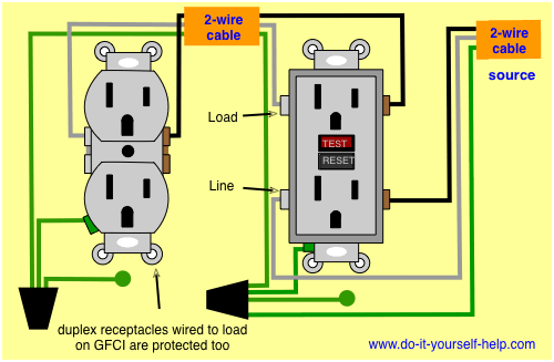
Wiring diagram for a switched gfci combo outlet. Omni surface type outlets are created with your safety and needs in mind. Wiring diagrams for a gfci bo switch best wiring diagram outlet. Connect the line cable's bare copper (or green) wire directly to the grounding terminal on the gfci receptacle. Have a new video on a channel
Wiring Diagrams For Electrical Receptacle Outlets Do It Yourself Help Com from www.do-it-yourself-help.com In this diagram, the switch built into the combo device is wired to control the gfci outlet itself. With all the electronic devices we use today, there never seems to be enough power outlets in a vehicle, especially if the car is a few years old. • for a box with a grounding terminal (diagram shown above): In this gfci outlet wiring and installation diagram, the combo (switch + outlet), spst (single way) switch and ordinary outlet is connected to the load side of gfci. Read this completely free guide on how to install a gfci outlet without ground and find out how to ground a 3 prong outlet that's not grounded. Getting started outlet amps and wiring. If anyone rides in the back seat, they are usually at a loss for some power. It means, all the connected loads to the load terminals of gfci are protected.
Any break or malfunction in one outlet will cause all the other outlets to fail.
The source neutral is connected the line neutral terminal. Switch and the outlet can have different lines in. For example , when a module will be powered up also it sends out a signal of fifty percent the voltage plus the technician will not know this, he would think he has a problem. Wiring diagram for a switched gfci combo outlet. Multiple outlet in serie wiring diagram : The only difference is that, depending on where the receptacle is located in the wiring scheme of your house, it may have more wires attached to it than you find attached to a light switch. Leviton presents how to install an electrical wall outlet. Leviton plug wiring diagram gallery. Don't folow this instructions, made some mistakes in a video. We tracked down an electrician who, not surprisingly, adds kitchen outlets all the time. In this diagram, the switch built into the combo device is wired to control the gfci outlet itself. Learn how to ground an outlet without ground wire plus more 2 prong to 3 prong tips. Ground connection diagram is shown separately.
The following project shows how to connect the receptacle when the electrical box has already been installed and. This circuit is used for a new clothes dryer outlet installation. He showed us how he adds an outlet to a kitchen backsplash by running conduit through the back of the cabinets. Connect the plug end of the wire harness to the empty plug on the main wire harness, located near the steering post, on the steering. This article explains that when there is no safe grounding conductor or ground wire at an electrical receptacle location you need to choose the proper receptacle type and make the proper wire connections for safety.
Wide Series Wwg 402 Omni Duplex Universal Outlet With Ground Wwg 402 from ayrosohardware.com.ph Getting started outlet amps and wiring. Wiring diagram for 220 outlet from i.ytimg.com to properly read a wiring diagram, one offers to learn how typically the components within the program operate. For wiring in series, the terminal screws are the means for passing voltage from one receptacle to another. Leviton presents how to install a decora bination device with for. Ground connection diagram is shown separately. Connect the red/white wire of the wire harness (pn 2411352) to the center (hot) terminal of the power outlet. This receptacle has a ground connection not found in the older 30 amp circuit for added protection against electrocution. For example , in case a module is usually powered up also it sends out a new signal of 50 percent the voltage and the technician does not know this, he would think he offers a problem, as.
For wiring in series, the terminal screws are the means for passing voltage from one receptacle to another.
• for a box with a grounding terminal (diagram shown above): He showed us how he adds an outlet to a kitchen backsplash by running conduit through the back of the cabinets. Don't folow this instructions, made some mistakes in a video. So before using the method we show here for how to wire a wall outlet in a kitchen or bathroom, check with an electrical inspector. The source hot wire is spliced with one of the switch wires and the other switch wire is connected to the hot line terminal on the device. The video covers how to strip electrical wire, create loops on the load, neutral, and ground wire, and how to. Wiring diagram for 220 outlet from i.ytimg.com to properly read a wiring diagram, one offers to learn how typically the components within the program operate. We tracked down an electrician who, not surprisingly, adds kitchen outlets all the time. Multiple outlet in serie wiring diagram : Ground connection diagram is shown separately. Connect the red/white wire of the wire harness (pn 2411352) to the center (hot) terminal of the power outlet. To wire multiple outlets, follow the circuit diagrams posted in this article. Leviton presents how to install a decora bination device with for.
Install an auxiliary power outlet in a vehicle: Don't folow this instructions, made some mistakes in a video. Getting started outlet amps and wiring. If you add an outlet to a kitchen or bath, it must be gfci protected. Connect the grounding wire (only if there is a grounding wire):
1 Gang Aircon Outlet Set Firefly Electric And Lighting Corporation from www.fireflyelectric.com Also connect a similar wire to the grounding terminal on the box. • for a box with a grounding terminal (diagram shown above): Install an auxiliary power outlet in a vehicle: The source hot wire is spliced with one of the switch wires and the other switch wire is connected to the hot line terminal on the device. Have a new video on a channel This is a newer version of the outdated 30 amp receptacle appearing in the previous diagram. Any break or malfunction in one outlet will cause all the other outlets to fail. Ground connection diagram is shown separately.
This receptacle has a ground connection not found in the older 30 amp circuit for added protection against electrocution.
Leviton gfci wiring diagram fresh wiring diagram for gfci receptacle. For example , in case a module is usually powered up also it sends out a new signal of 50 percent the voltage and the technician does not know this, he would think he offers a problem, as. Leviton plug wiring diagram gallery. Connect the brown wire of the wire harness to the outer (ground) terminal of the power outlet. If you add an outlet to a kitchen or bath, it must be gfci protected. The black wire (line) and white (neutral) connect to the receptacle terminals and another 2 wire nm that travels to the next receptacle. Any break or malfunction in one outlet will cause all the other outlets to fail. Have a new video on a channel Electrical wiring diagram electrical work electrical projects electrical outlets electrical engineering installing electrical outlet don chuy outlet wiring electric house. In this diagram, the switch built into the combo device is wired to control the gfci outlet itself. So before using the method we show here for how to wire a wall outlet in a kitchen or bathroom, check with an electrical inspector. Don't folow this instructions, made some mistakes in a video. How to wire a 3 prong plug and change your 2 prong outlet to a 3 prong outlet with ground.
Bagikan Artikel ini
Belum ada Komentar untuk "Outlet Wiring Diagram Omni Outlet Installation / Wiring Diagrams For Electrical Receptacle Outlets Do It Yourself Help Com / Electrical wiring diagram electrical work electrical projects electrical outlets electrical engineering installing electrical outlet don chuy outlet wiring electric house."


Belum ada Komentar untuk "Outlet Wiring Diagram Omni Outlet Installation / Wiring Diagrams For Electrical Receptacle Outlets Do It Yourself Help Com / Electrical wiring diagram electrical work electrical projects electrical outlets electrical engineering installing electrical outlet don chuy outlet wiring electric house."
Posting Komentar